
General Electric monogramGE Heritage Village
GE Heritage Village bulb logo

GE STEM Lab · Student course

Aviation & Propulsion

Identify four forces and use a simplified flight deck to compare balanced and unbalanced forces.

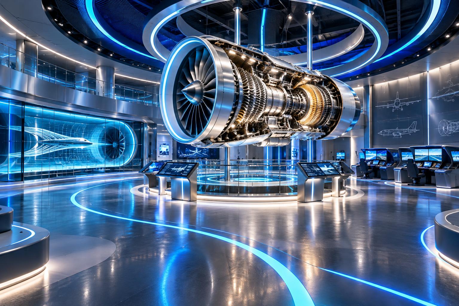
Original imagined learning zone · AI-assisted concept art, not a real GE facility.

Labeled system diagram · Aviation & Propulsion
1234Shaft links turbine to compressorAir →Exhaust →
  1. 1

    Air inlet

    Incoming air enters the core and the bypass passage.

  2. 2

    Compressor

    Shaft-driven blades increase the pressure of the core air.

  3. 3

    Combustor

    Fuel burns in compressed air, increasing its temperature.

  4. 4

    Turbine & exhaust

    The turbine extracts work to drive the compressor; the nozzle accelerates exhaust.

Original simplified teaching schematic—not to scale, an installation guide, a historical artifact or a complete technical blueprint.

✈️ HALL COURSE · 4 COMPLETE LESSONS

Aviation & Propulsion · learning syllabus

Identify four forces and use a simplified flight deck to compare balanced and unbalanced forces. Aerospace teams design aircraft, engines and flight-control systems.

Suggested 100 minutes · foundation explanations → worked examples → interactive experiments

Physics · Motion and forces · 20 suggested minutes

01 · Forces and aircraft motion

Learning objective: Relate balanced forces to motion and apply F = ma.

An aircraft in flight experiences weight, lift, thrust and drag. Weight is the gravitational force, W = mg, acting towards Earth. Lift is an aerodynamic force approximately perpendicular to the oncoming airflow; drag opposes relative motion through the air. Thrust comes from the propulsion system. Their directions need care when an aircraft turns or climbs.

Newton’s first law states that an object remains at rest or moves with constant velocity unless acted on by a resultant force. Balanced forces therefore do not require an aircraft to stop. In steady, straight, level flight, lift balances weight and thrust balances drag. Newton’s second law relates a resultant force to acceleration: F = ma.

A velocity changes if speed or direction changes. Turning requires acceleration even at constant speed. The virtual flight deck compares opposing forces, but it does not simulate realistic flight dynamics, stability or weather. Its readout is a model of force balance, not a prediction of altitude or a qualification to operate aircraft.

Worked example · follow the reasoning

A 1000 kg model aircraft has a forward resultant force of 2000 N. Its forward acceleration is a = F / m = 2 m/s². If thrust equals drag, forward acceleration is zero, not necessarily forward speed.

Common misconception

Zero resultant force means constant velocity, which can be nonzero.
Physics · Pressure; aviation enrichment · 25 suggested minutes

02 · Wings, pressure and control surfaces

Learning objective: Explain lift and distinguish pitch, roll and yaw.

Air flowing around a wing experiences changes in velocity and pressure. The pressure distribution and airflow deflection are connected aspects of the aerodynamic force. A wing can direct air downwards while experiencing an upward force. There is no rule requiring two air particles separated at a leading edge to meet again at the trailing edge.

Angle of attack is the angle between a wing reference line and the relative airflow. Increasing it can increase lift within an operating range. Beyond a critical angle, airflow separation can reduce lift substantially: this is a stall. A stall is not defined simply as an engine stopping. Lift also depends on air density, speed and wing geometry.

Pitch is rotation about the side-to-side axis, roll about the lengthwise axis and yaw about the vertical axis. Elevators, ailerons and rudders contribute to control; their effects interact. A flight deck also presents instruments for airspeed, altitude and attitude. These descriptions extend school physics into aviation, not flight training.

Worked example · follow the reasoning

If weight is 9800 N and lift is 9800 N in steady level flight, vertical resultant force is zero. Increasing lift above weight changes the vertical force balance; the actual response also depends on the aircraft’s state.

Common misconception

A stall concerns wing airflow and angle of attack, not necessarily engine failure.

Physics · Momentum and energy; engine enrichment · 25 suggested minutes

03 · Inside a jet engine

Learning objective: Trace airflow through compressor, combustor, turbine and exhaust.

Air enters a gas-turbine engine and is compressed, increasing pressure. Fuel is introduced in the combustor, where combustion transfers chemical energy into the hot gas. The gas expands through turbine stages, transferring energy to rotating shafts. Part of that work drives the compressor. The exhaust nozzle accelerates the remaining flow.

Thrust relates to changing the momentum of flowing air and exhaust; pressure differences can also contribute. Momentum p = mv. Newton’s third law describes paired forces acting on different objects: the engine pushes fluid backwards and the fluid pushes the engine forwards. These paired forces do not cancel on one aircraft because they act on different objects.

In a turbofan, a large front fan moves bypass air around the engine core. This bypass stream can provide much of the thrust, depending on the engine design. An aircraft gas turbine is related to a stationary gas turbine but designed for a different job. Real performance depends on airflow, pressure ratios, temperatures and operating limits.

Worked example · follow the reasoning

For a simplified pressure-matched jet with equal incoming and outgoing mass flow, 20 kg/s accelerated from 100 to 300 m/s gives momentum thrust 20 × (300 − 100) = 4000 N. Real engines also need fuel-flow and pressure terms.

Common misconception

The compressor uses work; it is not the component that directly supplies net shaft work to the outside system.

Mathematics · Graphs and proportional reasoning · 30 suggested minutes

04 · Flight calculations and design trade-offs

Learning objective: Interpret speed, acceleration and engineering comparisons.

Speed is distance travelled per time. Average speed = total distance / total time. On a distance–time graph, gradient represents speed. On a velocity–time graph, gradient represents acceleration and signed area represents displacement. Use SI units consistently, converting kilometres or minutes before calculations.

Engineers compare designs using evidence, not one “best” number. Reducing mass may reduce weight, but materials also require sufficient strength and fatigue resistance. More thrust may allow acceleration but also require more fuel or power. Noise, emissions, maintainability and reliability are separate considerations. State which variables are fixed in a comparison.

For a virtual investigation, predict the effect of changing thrust while keeping drag and mass fixed. Tabulate resultant forces and calculate accelerations. Then explain why drag is unlikely to stay fixed as a real aircraft accelerates. This evaluation is as important as the numerical result: a useful model can still omit important behaviour.

Worked example · follow the reasoning

A model travels 600 m in 30 s: average speed = 20 m/s. If velocity rises from 10 to 20 m/s in 5 s, average acceleration = (20 − 10) / 5 = 2 m/s².

Common misconception

A graph with horizontal velocity is not a graph showing zero movement; it shows constant velocity.

VISUAL SCIENCE NOTEBOOK

Aviation & Propulsion · how the system works

Process 1 · Thrust − drag → Acceleration
01Thrust − drag
02Resultant force
03F = ma
04Acceleration
Process 2 · Air inlet → Turbine + exhaust
01Air inlet
02Compressor
03Combustor
04Turbine + exhaust
Process 3 · Airflow → Aircraft response
01Airflow
02Wing pressure forces
03Lift
04Aircraft response

Process icons are conceptual symbols. Arrows show a selected energy, information or reasoning pathway—not scale, physical component positions or a complete engineering schematic. Use the lesson text and sources for the assumptions.

WATCH · PAUSE · EXPLAIN

Educational video lessons

Animagraffs

How Jet Engines Work

Animagraffs · metadata checked November 8, 2026

Turbofan airflow, compressor, combustion, turbines and bypass.

Watch on YouTube

Third-party lessons, not GE Heritage Village productions or partnerships. Loading a player connects to YouTube; external videos may contain advertising or become unavailable. Metadata checks identify the selected video, not certification of every statement. Original lesson sources remain the reference for calculations.

Young scientists · ages 8–12 with an adult

Aviation & Propulsion

Aerospace teams design aircraft, engines and flight-control systems.

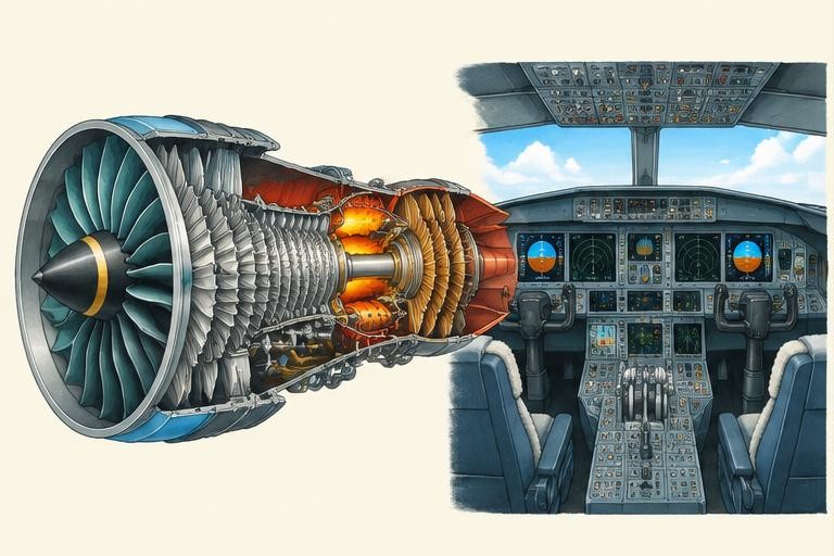
Original educational illustration: Aviation & Propulsion

Original AI-assisted educational illustration · numbered concept markers, not exact component locations or a technical blueprint.

A jet engine accelerates air and exhaust backwards, producing forward thrust. This is related to Newton’s third law.

Inside the flight deck

↑ Lift 50 kN← Drag 40 kN ✈ Thrust 40 kN →↓ Weight 50 kN
Forward net: 0 kN · Vertical net: 0 kN

Balanced! Straight, level, constant-speed flight in this model.

The science behind it

Newton’s second law: net force = mass × acceleration. Airflow and pressure help produce lift.

A conceptual flight deck, not flight training. Real aircraft motion depends on many interacting factors.

How things work · exploration library

Computing

How a CPU follows instructions

A processor follows machine instructions that operate on data. Conceptually, it fetches an instruction, decodes it and performs an operation. Modern processors overlap many operations, but an instruction set still defines what the machine can do. A CPU is not a tiny person making decisions.

Original explanation. For evidence and further reading, open the corresponding hall’s science references.

Science tutor

AI can make mistakes; check the lesson’s sources. Don’t share personal information. This conversation is not saved and disappears when you leave the page.

What would you like to understand about this science hall?

Original teaching materials and AI-assisted concept pictures. Selected IGCSE-style topics and engineering enrichment, not a complete accredited examination course. Volunteer education project, not official GE.

References & further reading

Selected syllabus references

Original British IGCSE-style lessons based on selected subject areas, not a complete exam course, official mapping of every objective, or Cambridge-endorsed material. Core/Supplement and Core/Extended requirements vary. MRI reconstruction, turbine cycles and specialist engineering are application enrichment beyond the underlying school topics. Check the current official syllabus for examination requirements. Video metadata identifies third-party lessons; it does not certify every spoken claim or license downloads.