







General Electric monogramGE Heritage Village
GE Heritage Village bulb logo

GE Heritage Village · Young scientists

GE STEM Lab

Science · Engineering · Exploration

Original imagined learning zone · AI-assisted concept art, not a real GE facility.

Read → Watch → Explore diagrams → Experiment

12 interactive halls · suggested syllabus 22.5 hours

Labeled system diagram · Electricity & Lighting
1234+ / −Current I →Complete conducting loop
  1. 1

    Battery

    Provides potential difference by transferring energy from a chemical store.

  2. 2

    Closed switch

    Completes the conducting path so current can flow.

  3. 3

    Resistive load

    Transfers electrical energy to heating and, for a lamp, light.

  4. 4

    Return wire

    Completes the circuit back to the battery; charge is not used up.

Original simplified teaching schematic—not to scale, an installation guide, a historical artifact or a complete technical blueprint.

⚡ HALL COURSE · 4 COMPLETE LESSONS

Electricity & Lighting · learning syllabus

Build a complete conducting loop and explain why a switch turns the light on or off. Electrical engineering powers lighting, appliances and factories.

Suggested 100 minutes · foundation explanations → worked examples → interactive experiments

Physics · Electricity · 20 suggested minutes

01 · Charge, current and potential difference

Learning objective: Distinguish charge, current and potential difference and use correct units.

An electric current is a rate of flow of charge. In metal wires, electrons move through the material; the wire is not used up. Conventional current is defined in the direction positive charge would flow, opposite to electron motion in a metal. Current is measured in amperes (A), charge in coulombs (C) and time in seconds (s). The relationship is I = Q / t.

Potential difference is energy transferred per unit charge between two points: V = E / Q. One volt means one joule is transferred for each coulomb. A battery provides a potential difference by transferring energy from its chemical store. Charge circulates around a complete circuit; energy is transferred by the electrical pathway to components.

An ammeter is connected in series so charge passes through it. A voltmeter is connected in parallel across the component whose potential difference is being measured. These are circuit-diagram conventions, not instructions for touching real electrical equipment. A complete conducting path and a source are needed for sustained current in this simple model.

Worked example · follow the reasoning

If 12 C passes a point in 4 s, I = 12 / 4 = 3 A. If a source transfers 18 J to 3 C of charge, V = 18 / 3 = 6 V. The first calculation describes flow; the second describes energy per charge.

Common misconception

A battery supplies energy; it does not manufacture the charge circulating in the wires.
Physics · Circuit relationships · 25 suggested minutes

02 · Resistance, series and parallel circuits

Learning objective: Calculate resistance and explain how connections affect current and voltage.

Resistance describes how strongly a component opposes current. R = V / I, with resistance measured in ohms (Ω). For an ohmic conductor at constant temperature, current is proportional to potential difference. An I–V graph is a straight line through the origin. This condition matters: a filament lamp heats up, changing its resistance, and a diode behaves differently.

In a series circuit, current is the same through each component because there is only one path. The source potential difference is shared between components, and resistances add: Rtotal = R1 + R2. Opening one part breaks the entire loop. In a parallel circuit, each branch has the same potential difference; current splits and the branch currents sum to the total.

For two parallel resistors, 1 / Rtotal = 1 / R1 + 1 / R2. Adding another branch lowers the total resistance, so an ideal fixed-voltage source supplies more total current. A scientific model specifies its assumptions: ideal wires, fixed resistor values and a source whose voltage does not fall under load.

Worked example · follow the reasoning

Two 10 Ω resistors in series give 20 Ω. Across 6 V, I = 6 / 20 = 0.30 A. In parallel they give 5 Ω, so total current is 6 / 5 = 1.20 A; each branch carries 0.60 A.

Common misconception

Current is not consumed by the first resistor; energy is transferred while charge continues around the loop.

Physics · Energy transfers · 25 suggested minutes

03 · Electrical power, energy and lighting

Learning objective: Use power and energy equations and interpret efficiency.

Power is the rate of energy transfer. P = E / t, so E = Pt. One watt is one joule per second. Electrical power is P = VI. Combining this with Ohm’s law gives P = I²R or P = V² / R for a resistor under the stated conditions. Energy and power are different: a low-power device running for a long time can transfer substantial energy.

A lamp transfers energy electrically into radiation and heating. Useful output depends on the purpose: visible light is useful for illumination, while heating is usually unwanted. Efficiency = useful energy output / total energy input, multiplied by 100% for a percentage. Conservation of energy still applies to inefficient devices; energy becomes less useful rather than disappearing.

LEDs and incandescent lamps create light by different mechanisms. A filament emits light when hot; an LED emits light through processes in a semiconductor. Our virtual circuit treats its load as a fixed resistor. It is not a realistic LED drive circuit and cannot establish a real lamp’s brightness or safe operating conditions.

Worked example · follow the reasoning

At 6 V and 0.20 A, P = 1.20 W. In 60 s, E = 1.20 × 60 = 72 J. If 18 J is useful light, efficiency = 18 / 72 × 100 = 25%.

Common misconception

An inefficient lamp does not destroy energy; more of its input is transferred to unwanted heating.

Physics · Practical skills · 30 suggested minutes

04 · Investigating an electrical model

Learning objective: Plan a fair test, organise readings and evaluate a model.

Ask a testable question: how does current vary with voltage for one fixed resistor? Voltage is the independent variable, current the dependent variable and resistance the controlled variable. State a prediction before collecting virtual readings. Use the same resistor and ideal-source assumptions throughout, changing one variable at a time.

Record readings in a table with units in headings, not mixed into numerical values. Plot current on the vertical axis and voltage on the horizontal axis. For a fixed resistor, the gradient of this I–V graph is 1 / R. Use more than two points so a pattern or anomalous result can be recognised. Do not assume every real device follows this straight-line relationship.

Evaluate separately what you observed and what the model assumes. A perfect simulation has no accidental measurement noise; a real experiment has instrument resolution, possible heating and connection effects. Repetition helps investigate variation but does not automatically remove systematic error. Only virtual or teacher-approved low-voltage activities belong in this lesson; never use household sockets.

Worked example · follow the reasoning

For 30 Ω, voltages 3, 6 and 9 V predict currents 0.10, 0.20 and 0.30 A. The graph gradient is 0.20 / 6 = 0.0333 A per V, equivalent to 1 / 30 Ω.

Common misconception

A straight line generated by a fixed-resistance simulation does not prove a real filament lamp has constant resistance.

VISUAL SCIENCE NOTEBOOK

Electricity & Lighting · how the system works

Process 1 · Chemical store → Light + heating
01Chemical store
02Battery voltage
03Closed circuit
04Light + heating
Process 2 · Source → Return path
01Source
02Series resistor 1
03Series resistor 2
04Return path
Process 3 · Voltage V → Energy Pt
01Voltage V
02Current I
03Power VI
04Energy Pt

Process icons are conceptual symbols. Arrows show a selected energy, information or reasoning pathway—not scale, physical component positions or a complete engineering schematic. Use the lesson text and sources for the assumptions.

WATCH · PAUSE · EXPLAIN

Educational video lessons

Khan Academy

Introduction to circuits and Ohm's law | Circuits | Physics | Khan Academy

Khan Academy · metadata checked November 8, 2026

Voltage, current, resistance and the fixed-resistor model.

Watch on YouTube

Third-party lessons, not GE Heritage Village productions or partnerships. Loading a player connects to YouTube; external videos may contain advertising or become unavailable. Metadata checks identify the selected video, not certification of every statement. Original lesson sources remain the reference for calculations.

Young scientists · ages 8–12 with an adult

Electricity & Lighting

Electrical engineering powers lighting, appliances and factories.

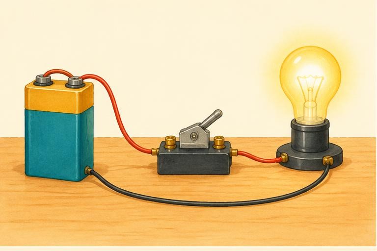
Original educational illustration: Electricity & Lighting○ Circuit open

Original AI-assisted educational illustration · numbered concept markers, not exact component locations or a technical blueprint.

A battery changes stored chemical energy into electrical energy and provides a voltage.

Light up an idea

No current · 0.00 A · 0.00 W

The load stays at 30 Ω. Predict what happens when voltage doubles, then test it.

The science behind it

Ohm’s law: I = V ÷ R for an ideal fixed resistor. Energy is transferred, not created.

Virtual low-voltage experiment only. Never experiment with wall outlets or mains electricity.

How things work · exploration library

Computing

How a CPU follows instructions

A processor follows machine instructions that operate on data. Conceptually, it fetches an instruction, decodes it and performs an operation. Modern processors overlap many operations, but an instruction set still defines what the machine can do. A CPU is not a tiny person making decisions.

Original explanation. For evidence and further reading, open the corresponding hall’s science references.

Science tutor

AI can make mistakes; check the lesson’s sources. Don’t share personal information. This conversation is not saved and disappears when you leave the page.

What would you like to understand about this science hall?

Original village lesson plans and AI-assisted concept illustrations, not a real facility, patient scan or historical GE artifact. Suggested ages and durations are editorial guidance, not accredited curriculum. A volunteer education project, not official GE.

References & further reading

Selected syllabus references

Original British IGCSE-style lessons based on selected subject areas, not a complete exam course, official mapping of every objective, or Cambridge-endorsed material. Core/Supplement and Core/Extended requirements vary. MRI reconstruction, turbine cycles and specialist engineering are application enrichment beyond the underlying school topics. Check the current official syllabus for examination requirements. Video metadata identifies third-party lessons; it does not certify every spoken claim or license downloads.