Physics · Energy · 20 suggested minutes
01 · Energy stores, transfers and efficiency
Learning objective: Trace energy pathways and calculate useful output.
Energy can be associated with kinetic, gravitational, chemical, thermal and other stores. It is transferred by mechanical work, electrical pathways, heating and radiation. Conservation of energy means the total remains accounted for. Avoid saying a generator creates energy: it transfers energy mechanically supplied by another system into an electrical pathway.
Power P = E / t describes the rate of transfer. Work done by a constant force along the displacement is W = Fd. Efficiency compares useful output with total input. The useful output depends on the system’s purpose. In a power plant, electricity is useful output, while heat rejected to surroundings may be unwanted unless deliberately recovered.
An energy diagram should label the initial store, each transfer pathway and useful and dissipated outputs. A turbine, generator and electrical load are different parts of the chain. Higher efficiency reduces the input needed for a given useful output, but environmental decisions also involve construction, fuel sourcing and operation.
Worked example · follow the reasoning
A generator receives 1000 J mechanically and supplies 850 J electrically. Efficiency = 850 / 1000 × 100 = 85%. The other 150 J is transferred to heating, sound and other losses.
Common misconception
“Renewable” does not mean no environmental impact, and “inefficient” does not mean energy has vanished.
Physics · Kinetic energy; turbine enrichment · 25 suggested minutes
02 · Wind turbines and available wind power
Learning objective: Explain aerodynamic rotation and compare available wind power.
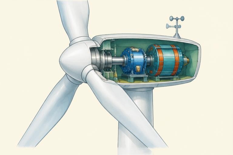
Wind carries kinetic energy. Aerodynamic forces on blades turn a rotor; a shaft connects this rotation to a generator, directly or through a gearbox depending on the design. Generator action is related to electromagnetic induction: a changing magnetic flux linkage can induce an electromotive force. The generator transfers mechanical energy into electrical energy.
For fixed air density and swept area, the available power in the airflow is proportional to v³. The full expression is Pwind = ½ρAv³, where ρ is air density, A swept area and v wind speed. This is available wind power, not electricity output. Only a fraction can be extracted and further losses occur in the machine.
Real turbines have cut-in, rated and cut-out conditions, plus controls for rotor speed and blade pitch. The power curve is not an unlimited cube law. Wind availability varies, so electricity systems need planning and flexible supply or demand. Land use, materials, wildlife and maintenance also belong in sustainability comparisons.
Worked example · follow the reasoning
If wind speed doubles from 4 to 8 m/s with density and area fixed, available power changes by (8 / 4)³ = 8. Electrical output need not increase eightfold.
Common misconception
A turbine cannot extract all kinetic energy from the wind passing through its rotor.
Physics · Thermal processes; turbine enrichment · 25 suggested minutes
03 · Gas turbines and combined cycles
Learning objective: Explain compression, combustion, expansion and heat recovery.
A gas turbine compresses incoming air, adds heat through combustion, then expands the hot gas through turbine blades. The compressor requires shaft work. Turbine work must cover that demand before useful net shaft work is available to drive a generator or other load. Energy leaves in useful output and hot exhaust, with other losses.
The ideal Brayton cycle is an enrichment model of gas-turbine operation: idealised compression and expansion with heat addition and rejection. It is not a complete description of a real plant. Changes in pressure, temperature and material limits affect performance. Fuel chemistry also affects emissions, and using a gas turbine does not itself make generation renewable.
A combined-cycle plant recovers some exhaust heat to generate steam, which drives a steam turbine and additional generation. Recovering heat can improve overall efficiency. However, all fuel input and outputs must be included in the system boundary; counting recovered energy twice gives a misleading result. This lesson is explanatory only: never handle fuel or machinery.
Worked example · follow the reasoning
If turbine shaft output is 80 MJ and the compressor consumes 50 MJ, net shaft work before other losses is 30 MJ. Compressor consumption cannot be ignored when reporting useful output.
Common misconception
Combustion adds thermal energy from fuel; the turbine and compressor are not interchangeable parts.
Mathematics · Percentages; scientific evaluation · 30 suggested minutes
04 · Comparing energy systems with evidence
Learning objective: Compare energy choices with a clear boundary and fair evidence.
Compare systems supplying the same useful output over the same period. A power rating tells the maximum or nominated transfer rate, not necessarily the actual energy supplied. Energy in kilowatt-hours is power in kilowatts multiplied by time in hours when power is constant. One kWh equals 3.6 million joules.
Operational emissions, construction impacts, fuel requirements, variability and reliability are different measures. A life-cycle comparison includes more than emissions at the generator. Separate evidence from opinion and specify whether a number describes one machine, a regional average or an assumed classroom case. Do not invent data for a real GE product.
For a design exercise, create a comparison table for wind and gas generation with energy source, conversion stages, operational fuel, variable availability and environmental issues. Explain why there may be more than one reasonable choice depending on context. A balanced evaluation acknowledges trade-offs instead of claiming one technology solves every problem.
Worked example · follow the reasoning
A 2 kW device running steadily for 3 h transfers 6 kWh, equivalent to 21.6 MJ. A 2 kW label alone does not tell its daily energy use.
Common misconception
A comparison using different time periods or different useful outputs is not automatically fair.
Physics · Energy resources; semiconductor enrichment · 25 suggested minutes
05 · Solar photovoltaic electricity
Learning objective: Explain solar cells, direct current and the energy transferred by sunlight.
The Sun releases energy through nuclear fusion. Radiation carries some of that energy through space to Earth. A photovoltaic (PV) cell transfers some incident radiation energy directly into electrical energy; it does not need a steam turbine. In a semiconductor, absorbed photons can produce mobile charge carriers. The cell’s internal electric field helps separate charges, allowing a connected circuit to receive electrical power. Semiconductor detail is enrichment beyond the basic energy-resource comparison.
Cells connect into modules and arrays. Their output is direct current (DC); an inverter supplies suitable alternating current (AC) where required. Solar irradiance is incident power per area in W/m². In a simplified model, electrical power = irradiance × illuminated area × efficiency fraction. Use watts for power and joules or kWh for energy. Angle, shading, temperature and electrical matching affect real output, so a classroom efficiency is not a product rating.
Explore the virtual panel by changing irradiance while keeping area and efficiency fixed, then compare areas at the same irradiance. Record the resulting power to reveal proportional relationships. PV operation does not burn fuel, but manufacture, land use, materials and end-of-life management have impacts. Clouds and night affect available radiation. Batteries store energy supplied earlier; they do not make sunlight available at night. Never connect real panels to mains wiring.
Worked example · follow the reasoning
At 800 W/m² across 2 m² with an assumed 20% conversion efficiency, output = 800 × 2 × 0.20 = 320 W. At constant output for 3 h, energy = 0.320 × 3 = 0.96 kWh. These are fictional model conditions, not guaranteed yield.
Common misconception
PV cells transfer radiation energy directly to electricity; they are not miniature heat engines.
Physics · Thermal physics and radiation · 25 suggested minutes
06 · Solar thermal energy and heat transfer
Learning objective: Distinguish solar heating from PV and apply specific heat capacity.
A solar thermal collector absorbs sunlight and transfers energy by heating a fluid. A dark absorber can absorb radiation effectively, while insulation reduces unwanted heat transfer. Conduction transfers energy through material; convection involves moving fluid; radiation does not require a medium. Domestic solar water heating and concentrating solar power are different applications. Concentrating systems use mirrors and heat to support a power cycle; ordinary PV cells do not operate by boiling water.
For a temperature change without a change of state, E = mcΔT, where m is mass in kg, c is specific heat capacity in J/(kg °C) and ΔT is temperature change. Heating water to boiling and changing liquid into steam are different processes: latent heat must also be accounted for during the change of state. The simple temperature-rise example assumes constant heat capacity and omits evaporation, container heating and losses.
A controlled classroom model compares energy received by equal masses under equal illumination times. A real collector loses heat as its temperature rises above its surroundings, so a linear model cannot predict unlimited heating. Compare PV and solar thermal by useful output, not just by the word solar. Only use the on-screen model or teacher-approved cool-water demonstrations; do not focus sunlight with mirrors or lenses, use hot collectors or create steam pressure.
Worked example · follow the reasoning
Using c = 4200 J/(kg °C), raising 1 kg of water by 5 °C requires 21000 J. An ideal 100 W heating input would take 210 s. Real heating takes longer when losses and container heating are included.
Common misconception
A solar water heater and a photovoltaic panel deliver different useful outputs.
Physics · Gravitational energy, power and induction · 25 suggested minutes
07 · Hydroelectricity, water head and pumped storage
Learning objective: Trace reservoir energy through a turbine and calculate idealised output.
Water at height has a gravitational potential-energy store relative to a lower level. E = mgh describes the change in that store for a mass m moving down height h near Earth’s surface. A penstock guides water towards a turbine. Moving water transfers energy mechanically to the rotor; a generator transfers shaft work into electricity by electromagnetic induction. Water continues downstream through a tailrace. Generators do not turn water into electrical matter.
For steady flow, ideal available hydraulic power is P = ρgQh, where water density ρ is approximately 1000 kg/m³, Q is volume flow rate in m³/s, h is effective head in metres and g is approximately 9.8 N/kg. Multiply by an assumed overall efficiency for useful electrical output. This is an enrichment extension of energy and power equations. Actual head losses, turbine operating limits and variable flows must be considered.
Hydropower can use reservoirs or flowing rivers. Rainfall and the wider water cycle replenish supplies; output still depends on water availability. Dams can change habitats, fish migration, sediment and communities. Pumped storage uses electricity to move water uphill, then recovers some energy later; losses mean less electricity is returned than consumed. It is energy storage, not a new primary source. Use the virtual head-and-flow experiment; never approach dams, waterways or turbines.
Worked example · follow the reasoning
At Q = 0.10 m³/s, h = 10 m and assumed efficiency 80%, useful power = 1000 × 9.8 × 0.10 × 10 × 0.80 = 7840 W = 7.84 kW. Doubling head doubles this model output only if flow and efficiency stay fixed.
Common misconception
Pumped storage cannot return more energy than was supplied to pump the water uphill.
Physics · Nuclear physics · 25 suggested minutes
08 · Atoms, isotopes and ionising radiation
Learning objective: Distinguish nuclear particles, isotopes and alpha, beta and gamma radiation.
An atom has a tiny nucleus containing protons and usually neutrons, surrounded by electrons. Proton number identifies the element. Nucleon number counts protons plus neutrons. Isotopes are atoms of the same element with different neutron numbers. Uranium-235 therefore has 92 protons and 143 neutrons. Chemical reactions rearrange electrons and bonds; nuclear changes affect nuclei. These are different mechanisms even when both can transfer energy.
Unstable nuclei can decay spontaneously and randomly. Alpha radiation consists of helium nuclei, beta-minus radiation involves emitted electrons produced in a nuclear transformation, and gamma radiation is electromagnetic radiation. Penetration and ionising ability differ: alpha is readily stopped externally but can be dangerous inside the body, while gamma is more penetrating. Shielding reduces exposure rather than making every situation harmless. Irradiation and contamination are not the same: contamination involves radioactive material being present.
Radiation is used in medicine and industry under controlled conditions. Safety considers exposure time, distance and suitable shielding, together with professional regulation. A school explanation is not permission to handle sources. Count rate from a detector includes background and fluctuates, so corrected results and repeated readings require care. This hall only uses a mathematical decay illustration; never obtain radioactive materials, dismantle detectors or perform radiation experiments without authorised supervision.
Worked example · follow the reasoning
For uranium-235, neutron number = 235 − 92 = 143. Uranium-238 has 146 neutrons but the same 92 protons. The isotope changes, not the chemical element; this calculation describes structure, not a fuel-handling procedure.
Common misconception
Gamma radiation is an electromagnetic wave, not a particle made of protons and neutrons.
Physics · Nuclear energy and radioactive decay · 25 suggested minutes
09 · Nuclear fission, reactors and half-life
Learning objective: Explain controlled fission, heat-to-electricity pathways and statistical half-life.
In fission, a heavy nucleus splits into smaller nuclei, releasing energy and typically neutrons. A neutron absorbed by uranium-235 can initiate fission; released neutrons can cause further events in a chain reaction. A reactor controls this process. Control rods absorb neutrons; a moderator slows neutrons in designs that require it; coolant transports heat. These roles must not be confused. Fusion joins light nuclei and powers the Sun; it is not the process in conventional fission power stations.
Reactor heat supports steam production, a steam turbine and an electrical generator, with cooling needed to reject energy. Reactor designs differ: a boiling-water reactor and a pressurised-water reactor do not have identical steam circuits. A simplified pathway cannot describe every layout. Nuclear fuels are nonrenewable resources, and radioactive waste needs careful long-term management. Low operational carbon emissions do not mean no mining, construction or waste impacts.
Half-life is the time for the expected number of undecayed nuclei, or activity, to fall to half its original value. Individual decay times cannot be predicted. After n half-lives, expected remaining quantity is N₀ × (½)ⁿ. Activity is measured in becquerels, decays per second, not the same as radiation dose. The virtual model shows expectation, not exact measured counts. Reactor cooling remains important after shutdown because decay heat continues; this is explanation only, never reactor-operation guidance.
Worked example · follow the reasoning
For a fictional sample with 800 undecayed nuclei initially, the expected number after three half-lives is 800 × (½)³ = 100. This is a statistical expectation; it does not predict which nuclei decay or an exact real count.
Common misconception
Half-life does not mean every nucleus disappears after two half-lives; one-quarter is expected to remain.
Physics · Energy-resource evaluation; systems enrichment · 25 suggested minutes
010 · Energy resources, storage and electricity systems
Learning objective: Compare wind, solar, hydro, gas and nuclear with fair system boundaries.
An electricity system balances supply and demand over time. Power is the instantaneous transfer rate; energy is accumulated over an interval. Solar and wind depend on available natural conditions. Hydropower depends on water resources and plant design; nuclear and gas plants also have operating limits, maintenance and fuel requirements. Dispatchability means output can be scheduled or adjusted within constraints, not that every plant can change output instantly.
Storage shifts energy between times and always involves losses. Batteries store energy electrochemically; pumped storage raises water. Transmission also has losses: for a conductor, heating power is I²R. Transformers change AC voltage; transmitting a given power at higher voltage can reduce current and resistive heating, subject to real system design. Electricity is an energy carrier, not a primary fuel. The grid connects different conversion and storage technologies.
Compare the same delivered energy and state boundaries: operational emissions differ from lifecycle impacts. Consider reliability, location, costs, safety, waste, habitats, fuel security and demand reduction without invented real-world statistics. Renewable resources are replenished naturally, not impact-free; nuclear fuel is finite despite low operational carbon emissions. The examples are general science, not claims that GE invented each energy source or that a successor company remains part of former GE.
Worked example · follow the reasoning
A fictional store accepts 10 kWh and returns 8 kWh: round-trip efficiency = 8 / 10 × 100 = 80%. A 2 kW constant load could run for 4 h on the returned energy, ignoring any additional inverter losses.
Common misconception
A plant’s rated power does not determine the actual energy it delivers over a day.